Aqualink Wiring Diagram - Jika kamu sedang mencari artikel Aqualink Wiring Diagram terbaru, berarti kamu sudah berada di website yang benar. Setiap artikel diulas secara mendetail dengan penyajian bahasa yang ringan dipahami bagi orang awam sekalipun. itulah sebabnya web ini banyak diminati para blogger dan pembaca online. Yuk langsung saja kita simak pembahasan Aqualink Wiring Diagram berikut ini.
Aqualink Wiring Diagram. Shared Heater Check Valves 4 Spa Intake Spa Filter Spa Return Spa Pump Pool Intake Pool Pump Pool Filter Pool Return JVA JVA JVA To Solar if installed. Schematic Wiring Diagram and Worksheets Resource Aqualink Wiring Diagram. The Jandy Pool and Spa lights are intended for installation in fresh water and non-fresh. ORPExternal Control Connector AquaLink RS485 Connector CAUTION Factory wired for 240 VAC service. Jandy Aqualink Rs Wiring Diagram - Follow the wiring diagram in the AquaLink RS installation manual for connections.
Otg Usb Cable Wiring Diagram By Dave Rongey Summary. 8 AWG 4115mm copper wire to any metal ladders water pipes or other metal within five 5 feet 152m of the tub. PLEASE SUBSCRIBE for more helpful videosWhy is this happening. In addition a second wire connector should be bonded with a no. Board Wiring Diagram on the inside of the Power Center door to locate the Four Function Remote terminals. NOTE When the filter system is shared a PoolSpa Combo the spa water must be able to overflow back to the pool.
I also have 2 pool lights and 1 spa light going to controller.
Motorola Astro Radio Wiring Diagram If wire run low Voltage is more than 300 feet larger wire should be used. Shared Heater Check Valves 4 Spa Intake Spa Filter Spa Return Spa Pump Pool Intake Pool Pump Pool Filter Pool Return JVA JVA JVA To Solar if installed. The Jandy AquaLink RS is a multi-function pool controller that can fully control the. I have aqualink RS8main pump booster pump heater blower and 2 actuatorscontrolling pool spa and water feature. Board is now included with the Four. AquaLink RS and PDA Hardware Upgrades This section applies to older AquaLink systems.
By Dave Rongey Summary.
6 Wire Trailer Plug Diagram The Jandy AquaLink RS is a multi-function pool controller that can fully control the. Board over to the heater and wire in series with the heater circuitry as if you were wiring a firemans switch or heater delay. By Dave Rongey Summary. Separate the black wire common from each other see diagram at right. In addition a second wire connector should be bonded with a no.
31 Replacement of the CPU Board This step is for the AquaLink RS with revision N firmware or newer ONLY.
23 Hp Briggs Vanguard Wiring Diagram NOTE When connecting to the AquaLink RS plug the JVAs into the Intake Return and Cleaner JVA sockets. See wiring diagram in Section 4 Figure 5. Separate the black wire common from each other see diagram at right. Shared Heater Check Valves 4 Spa Intake Spa Filter Spa Return Spa Pump Pool Intake Pool Pump Pool Filter Pool Return JVA JVA JVA To Solar if installed. The Jandy AquaLink RS is a multi-function pool controller that can fully control the. In addition a second wire connector should be bonded with a no.
The Jandy AquaLink RS is a multi-function pool controller that can fully control the.
Case 621 Wiring Diagram The cable jacket 4 and strip each wire ¼. I also have 2 pool lights and 1 spa light going to controller. 31 Replacement of the CPU Board This step is for the AquaLink RS with revision N firmware or newer ONLY. The cable jacket 4 and strip each wire ¼. AquaLink Z4 Owners Manual H0386600 DOWNLOAD View i Q900 iQ900 Web-Connect Device Quick Start Guide H0365300.
Wire the remote according to the diagram.
197Vw Wiper Motor Wiring Diagram Board Wiring Diagram on the inside of the Power Center door to locate the Four Function Remote terminals. Jandy Aqualink Control Panel Wiring Diagram It is far more helpful as a reference guide if anyone wants to know about the homes electrical system. AquaLink RS485 Connector External Control. Figure 2 Figure 2. VAC Wiring Diagram for the AquaLink RS PureLinkTM System. See wiring diagram in Section 4 Figure 5.
Figure 2 Figure 2.
Hatz Engine Diagram Separate the black wire common from each other see diagram at right. For AquaLink RS rev R or later or AquaLink PDA rev 60 or later skip to section 4 of this manual. Our dog bit into the wire that runs from the pool computer box outside to the control panel inside my home. Shared Heater Check Valves 4 Spa Intake Spa Filter Spa Return Spa Pump Pool Intake Pool Pump Pool Filter Pool Return JVA JVA JVA To Solar if installed. Equipment but no smaller than no.
SAVE THESE INSTRUCTIONS Attention installer.
Masthead Light Wiring Diagram Wire the remote according to the diagram. The cable jacket 4 and strip each wire ¼. PLEASE SUBSCRIBE for more helpful videosWhy is this happening. NOTE When connecting to the AquaLink RS plug the JVAs into the Intake Return and Cleaner JVA sockets. If wire run low Voltage is more than 300 feet larger wire should be used. AquaLink Z4 - all revisions will work Section 3.
Remove the heater service door.
1954 Ford 8n Wiring Diagram Find manuals for all connected pool products by Zodiac Jandy and AquaLink. Jandy Aqualink Control Panel Wiring Diagram It is far more helpful as a reference guide if anyone wants to know about the homes electrical system. ORPExternal Control Connector AquaLink RS485 Connector CAUTION Factory wired for 240 VAC service. Slide DIP Switch S1-6 to the ON position. Figure 2 Figure 2.
AquaLink Z4 - all revisions will work Section 3.
Sine Wave Inverter Oscillator Circuit Diagram Wiring to an AquaLink RS Control System9. Schematic Wiring Diagram and Worksheets Resource Aqualink Wiring Diagram. If available electrical service is 120 VAC the power supply wiring must be changed to operate on 120 VAC as shown in the wiring diagram below. Our dog bit into the wire that runs from the pool computer box outside to the control panel inside my home. How to run your Pentair Intelliflo pump off of a Jandy Aqualink control panel. For AquaLink RS rev R or later or AquaLink PDA rev 60 or later skip to section 4 of this manual.
I also have 2 pool lights and 1 spa light going to controller.
1999 Ford F 250 Super Duty Wiring Diagram Shared Heater Check Valves 4 Spa Intake Spa Filter Spa Return Spa Pump Pool Intake Pool Pump Pool Filter Pool Return JVA JVA JVA To Solar if installed. AquaLink RS and PDA Hardware Upgrades This section applies to older AquaLink systems. NOTE When connecting to the AquaLink RS plug the JVAs into the Intake Return and Cleaner JVA sockets. Shared Heater Check Valves 4 Spa Intake Spa Filter Spa Return Spa Pump Pool Intake Pool Pump Pool Filter Pool Return JVA JVA JVA To Solar if installed. Wire the remote according to the diagram.
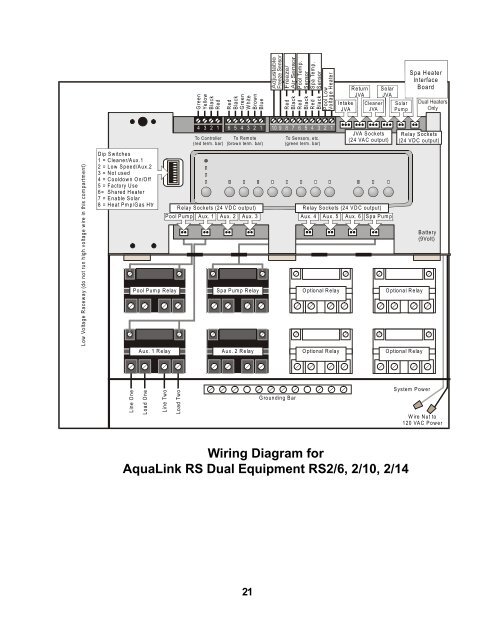
If available electrical service is 120 VAC the power supply wiring must be changed to operate on 120 VAC as shown in the wiring diagram below.
Cat5e Wall Plug Wiring Diagram NOTE When the filter system is shared a PoolSpa Combo the spa water must be able to overflow back to the pool. Board is now included with the Four. Is the least efficient diagram among the electrical wiring diagram. Equipment but no smaller than no. Page 14 33 Low Voltage Wiring Minimum wire size should be 22 AWG. AquaLink RS and PDA Hardware Upgrades This section applies to older AquaLink systems.
VAC Wiring Diagram for the AquaLink RS PureLinkTM System.
5 Wire Ceiling Fan Capacitor Wiring Diagram I have aqualink RS8main pump booster pump heater blower and 2 actuatorscontrolling pool spa and water feature. Slide DIP Switch S1-6 to the ON position. Page 14 33 Low Voltage Wiring Minimum wire size should be 22 AWG. AquaLink Z4 Owners Manual H0386600 DOWNLOAD View i Q900 iQ900 Web-Connect Device Quick Start Guide H0365300. Wiring to an AquaLink RS Control System9.
Board over to the heater and wire in series with the heater circuitry as if you were wiring a firemans switch or heater delay.
Jetta Fuse Box Diagram 2011 31 Replacement of the CPU Board This step is for the AquaLink RS with revision N firmware or newer ONLY. Bring two heater wires from the AquaLink RS PC. NOTE When connecting to the AquaLink RS plug the JVAs into the Intake Return and Cleaner JVA sockets. AquaLink Z4 - all revisions will work Section 3. The Jandy AquaLink RS is a multi-function pool controller that can fully control the. AquaLink RS485 Connector External Control.
AquaLink Z4 - all revisions will work Section 3.
Aprilia Sr 50 Factory Wiring Diagram AquaLink RS Indoor Controllers Wiring Diagram 9 Figure 5. Find manuals for all connected pool products by Zodiac Jandy and AquaLink. My main pump 3HP relay keeps blowing and I need to see a wiring schematic for this set up to confirm the correct way to hook this all up. Plug in the red terminal bar and hang the controller on the back of the housing then go to the power centerJandy Aqualink Wiring Diagram Wiring LibraryJANDY AQUALINK RS INSTALLATION MANUAL Pdf Download. AquaLink Z4 Owners Manual H0386600 DOWNLOAD View i Q900 iQ900 Web-Connect Device Quick Start Guide H0365300.
I have aqualink RS8main pump booster pump heater blower and 2 actuatorscontrolling pool spa and water feature.
Thomas Bus Wiring Diagrams The cable jacket 4 and strip each wire ¼. In addition a second wire connector should be bonded with a no. AquaLink RS and PDA Hardware Upgrades This section applies to older AquaLink systems. If wire run low Voltage is more than 300 feet larger wire should be used. Jandy Aqualink Control Panel Wiring Diagram It is far more helpful as a reference guide if anyone wants to know about the homes electrical system. 31 Replacement of the CPU Board This step is for the AquaLink RS with revision N firmware or newer ONLY.
Board over to the heater and wire in series with the heater circuitry as if you were wiring a firemans switch or heater delay.
Diagrams Les Paul Wiring The Jandy Pool and Spa lights are intended for installation in fresh water and non-fresh. Plug in the red terminal bar and hang the controller on the back of the housing then go to the power centerJandy Aqualink Wiring Diagram Wiring LibraryJANDY AQUALINK RS INSTALLATION MANUAL Pdf Download. AquaLink Z4 - all revisions will work Section 3. SAVE THESE INSTRUCTIONS Attention installer. For AquaLink RS rev R or later or AquaLink PDA rev 60 or later skip to section 4 of this manual.
Situs ini adalah komunitas terbuka bagi pengguna untuk menuangkan apa yang mereka cari di internet, semua konten atau gambar di situs web ini hanya untuk penggunaan pribadi, sangat dilarang untuk menggunakan artikel ini untuk tujuan komersial, jika Anda adalah penulisnya dan menemukan gambar ini dibagikan tanpa izin Anda, silakan ajukan laporan DMCA kepada Kami.
Jika Anda menemukan situs ini lengkap, tolong dukung kami dengan membagikan postingan ini ke akun media sosial seperti Facebook, Instagram dan sebagainya atau bisa juga bookmark halaman blog ini dengan judul Aqualink Wiring Diagram dengan menggunakan Ctrl + D untuk perangkat laptop dengan sistem operasi Windows atau Command + D untuk laptop dengan sistem operasi Apple. Jika Anda menggunakan smartphone, Anda juga dapat menggunakan menu laci dari browser yang Anda gunakan. Baik itu sistem operasi Windows, Mac, iOS, atau Android, Anda tetap dapat menandai situs web ini.