Buffer Tank Wiring Diagram Hss - Jika kamu mencari artikel Buffer Tank Wiring Diagram Hss terlengkap, berarti kamu telah berada di web yang benar. Setiap artikel diulas secara tuntas dengan penyajian bahasa yang ringan dimengerti bagi orang awam sekalipun. itulah sebabnya web ini banyak diminati para blogger dan pembaca online. Yuk langsung aja kita simak penjelasan Buffer Tank Wiring Diagram Hss berikut ini.
Buffer Tank Wiring Diagram Hss. Mains supply 230V AC from B16 circuit breaker or 13A fused spur Hot water cylinder. Units are provided with wiring diagrams and name plate data to provide information required for necessary field wiring. 37kW Isolator 20A double pole Relay Sensor Board optional add-on for eddi. Water runs out of the top of the HSS Buffer Tank 1. An immersion temperature control well is located in the middle of the tank to ensure accurate temperature sensing for heating and geothermal applications along with a conveniently located.
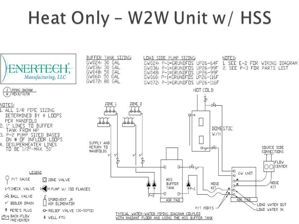
110 Block Rj45 Wiring Diagram The piping shown in Figures 12 and 3 all involve four principal piping connections to the buffer tank two into the upper portion and two into the lower portion. Heating diagrams A collection of hydraulic drawings of established installation. Air in zones will cause water to over flow when pumps are shut off. A water line leak above the height of the Buffer Tank could cause air to enter and allow the water to run out. The HSS Air Handlers are provided with a Class 2 transformer or 24-volt control circuits. The HSS Air Handlers are provided with a Class 2 transformer or 24-volt control circuits.
HSS - Hydronic System Solutions Slash system design time with collection of interactive tools and design an entire LoadMatch system within 30 minutes.
Diagram Samsung S4 Units are provided with wiring diagrams and name plate data to provide information required for necessary field wiring. Guitar Pickups Bass Pickups Pedals. An immersion temperature control well is located in the middle of the tank to ensure accurate temperature sensing for heating and geothermal applications along with a conveniently located. Boiler Blow Down Tanks CBO Flash Tanks FST Condensate Mixers CM Non-Electric Condensate Pumps CCP Heat Recovery HRS Replacement Tube Bundles RTB Commercial Electric Boilers. Specification Technical Parameters of Arctic Air to Water Heat Pumps Model MAFP020A MAFP040A MAFP060A Rated Cooling Capacity kW ① 75 150 125 RatedInputPowerkW① 30 41 6 Rated Input Current A ① 1363 1863 273 PerformanceCOPWW① 25 25 25 Rated Heating Capacity kW ② 105 160 20 RatedInputPowerkW② 283 441 554. Thermostat Forced Air Electric auxiliary heater Optional Air Pad Buffer Tank Pressurized or HSS Load Side Pump Aquastat hydronic control Flow Center Pressurized Non-Pressurized Hose kit.
The HSS Air Handlers are provided with a Class 2 transformer or 24-volt control circuits.
2007 Toyota Rav4 Wiring Diagrams Download The piping shown in Figures 12 and 3 all involve four principal piping connections to the buffer tank two into the upper portion and two into the lower portion. Mains supply 230V AC from B16 circuit breaker or 13A fused spur Hot water cylinder. Heat Pump with Water Heating and Buffer Tank. Key for Wiring Diagram 12. The HSS Air Handlers are provided with a Class 2 transformer or 24-volt control circuits.
HSS - Hydronic System Solutions Slash system design time with collection of interactive tools and design an entire LoadMatch system within 30 minutes.
Wiring Diagram For 1998 Dodge Ram 1500 Boiler Blow Down Tanks CBO Flash Tanks FST Condensate Mixers CM Non-Electric Condensate Pumps CCP Heat Recovery HRS Replacement Tube Bundles RTB Commercial Electric Boilers. The HSS Air Handlers are provided with a Class 2 transformer or 24-volt control circuits. 37kW Isolator 20A double pole Relay Sensor Board optional add-on for eddi. HSS - Hydronic System Solutions Slash system design time with collection of interactive tools and design an entire LoadMatch system within 30 minutes. Units are provided with wiring diagrams and name plate data to provide information required for necessary field wiring. The hydronic buffer tanks are available in sizes ranging from 10-119 gallons and is manufactured with four 15 tappings for primarysecondary connections.
Air in zones will cause water to over flow when pumps are shut off.
Wiring Diagram Vw Crafter Water runs out of the top of the HSS Buffer Tank 1. Geo-Flo Hydro-Connect Buffer TankControl System Geo-Flo Corporation 905 Williams Park Drive Bedford Indiana 47421 Main Number. Specification Technical Parameters of Arctic Air to Water Heat Pumps Model MAFP020A MAFP040A MAFP060A Rated Cooling Capacity kW ① 75 150 125 RatedInputPowerkW① 30 41 6 Rated Input Current A ① 1363 1863 273 PerformanceCOPWW① 25 25 25 Rated Heating Capacity kW ② 105 160 20 RatedInputPowerkW② 283 441 554. Boiler Blow Down Tanks CBO Flash Tanks FST Condensate Mixers CM Non-Electric Condensate Pumps CCP Heat Recovery HRS Replacement Tube Bundles RTB Commercial Electric Boilers. Units are provided with wiring diagrams and name plate data to provide information required for necessary field wiring.
37kW Isolator 20A double pole Relay Sensor Board optional add-on for eddi.
Toyota Jbl Lifier Wiring Diagram Picture All system components from Solarbayer including a wood gasifying boiler stratification buffer tanks solar DHW tank and a thermal solar system with flat plate collectors. Units are provided with wiring diagrams and name plate data to provide information required for necessary field wiring. Specification Technical Parameters of Arctic Air to Water Heat Pumps Model MAFP020A MAFP040A MAFP060A Rated Cooling Capacity kW ① 75 150 125 RatedInputPowerkW① 30 41 6 Rated Input Current A ① 1363 1863 273 PerformanceCOPWW① 25 25 25 Rated Heating Capacity kW ② 105 160 20 RatedInputPowerkW② 283 441 554. It doesnt usually contain any coils or heat exchangers. HSS Pickups 1 Volume 1 Tone Humbucker split with the middle pickup in the 4 position Ability for the single coils to see 250k pots and humbucker to see 500k pot Ive found this wiring diagram I think this is from Suhr that seems to accomplish everything I want. Guitar Pickups Bass Pickups Pedals.
Although these principal connections can function well they are not the only way to connect a buffer tank into the system.
Headlight Wiring Diagram For 2000 Gmc Sonoma Its an excellent way to harvest heat from any thermal. Weve discussed the latter in several previous columns. An immersion temperature control well is located in the middle of the tank to ensure accurate temperature sensing for heating and geothermal applications along with a conveniently located. All wiring must comply with local and national code requirements. Heat Pump with Water Heating and Buffer Tank.
Mains supply 230V AC from B16 circuit breaker or 13A fused spur Hot water cylinder.
Toyota Audio Wiring Diagram Buffer Tank Aqua-stat W2W Unit Flow Center Zone Pumps Manifolds Tubing. It doesnt usually contain any coils or heat exchangers. Cement Lined Storage Tanks CST Jacketed Storage Tanks JST Chilled Water Buffer Tanks CWB System Efficiency Buffer Tank SEB Steel Tanks. Guitar Pickups Bass Pickups Pedals. HSS - Hydronic System Solutions Slash system design time with collection of interactive tools and design an entire LoadMatch system within 30 minutes. Key for Wiring Diagram 12.
Buffer tanks shouldnt be confused with thermal stores as they are not a substitute for a hot water cylinder.
Peterbilt 379 Engine Fan Diagram Heat Pump with Water Heating and Buffer Tank. Knockouts are provided on the cabinet for connection of power supply. An immersion temperature control well is located in the middle of the tank to ensure accurate temperature sensing for heating and geothermal applications along with a conveniently located. HBX ECOHBX ECO--1000 Wiring Diagram 2stg 1000 Wiring Diagram 2stg. A buffer tank is typically just an insulated vessel of water.
Specification Technical Parameters of Arctic Air to Water Heat Pumps Model MAFP020A MAFP040A MAFP060A Rated Cooling Capacity kW ① 75 150 125 RatedInputPowerkW① 30 41 6 Rated Input Current A ① 1363 1863 273 PerformanceCOPWW① 25 25 25 Rated Heating Capacity kW ② 105 160 20 RatedInputPowerkW② 283 441 554.
Wiring Diagram For 2011 Toyota Camry HSS Pickups 1 Volume 1 Tone Humbucker split with the middle pickup in the 4 position Ability for the single coils to see 250k pots and humbucker to see 500k pot Ive found this wiring diagram I think this is from Suhr that seems to accomplish everything I want. The HSS Air Handlers are provided with a Class 2 transformer or 24-volt control circuits. Taco offers these tanks in sizes from 50 gallons up through 3000 gallons across 22 tank volumes. 37kW Isolator 20A double pole Relay Sensor Board optional add-on for eddi. Guitar Pickups Bass Pickups Pedals. Geo-Flo Hydro-Connect Buffer TankControl System Geo-Flo Corporation 905 Williams Park Drive Bedford Indiana 47421 Main Number.
Cement Lined Storage Tanks CST Jacketed Storage Tanks JST Chilled Water Buffer Tanks CWB System Efficiency Buffer Tank SEB Steel Tanks.
Variable Transformer Wiring Diagram Picture High Voltage Wiring Diagrams 7 Low VoltageThermostat Wiring Diagrams Applications 9. Geo-Flo Hydro-Connect Buffer TankControl System Geo-Flo Corporation 905 Williams Park Drive Bedford Indiana 47421 Main Number. HSS - Hydronic System Solutions Slash system design time with collection of interactive tools and design an entire LoadMatch system within 30 minutes. Taco offers these tanks in sizes from 50 gallons up through 3000 gallons across 22 tank volumes. Buffer Tanks are often employed within HVAC systems to provide additional system fluid volume in order to prevent short cycling of heating or cooling apparatus.
Knockouts are provided on the cabinet for connection of power supply.
Camaro 82 Wiring Diagram HSS - Hydronic System Solutions Slash system design time with collection of interactive tools and design an entire LoadMatch system within 30 minutes. Cement Lined Storage Tanks CST Jacketed Storage Tanks JST Chilled Water Buffer Tanks CWB System Efficiency Buffer Tank SEB Steel Tanks. The HSS Air Handlers are provided with a Class 2 transformer or 24-volt control circuits. Air in zones will cause water to over flow when pumps are shut off. Its an excellent way to harvest heat from any thermal. Heat Pump with Water Heating and Buffer Tank.
Buffer Tanks are often employed within HVAC systems to provide additional system fluid volume in order to prevent short cycling of heating or cooling apparatus.
Golf Cart Motor Wiring Diagram Boiler Blow Down Tanks CBO Flash Tanks FST Condensate Mixers CM Non-Electric Condensate Pumps CCP Heat Recovery HRS Replacement Tube Bundles RTB Commercial Electric Boilers. It doesnt usually contain any coils or heat exchangers. An immersion temperature control well is located in the middle of the tank to ensure accurate temperature sensing for heating and geothermal applications along with a conveniently located. HSS Pickups 1 Volume 1 Tone Humbucker split with the middle pickup in the 4 position Ability for the single coils to see 250k pots and humbucker to see 500k pot Ive found this wiring diagram I think this is from Suhr that seems to accomplish everything I want. Thermostat Forced Air Electric auxiliary heater Optional Air Pad Buffer Tank Pressurized or HSS Load Side Pump Aquastat hydronic control Flow Center Pressurized Non-Pressurized Hose kit.
A NON-PRESSURIZED STAINLESS STEEL BUFFER TANK FOR HYDRONIC HEAT.
Jackson Emg Pickups Wiring Diagrams Boiler Blow Down Tanks CBO Flash Tanks FST Condensate Mixers CM Non-Electric Condensate Pumps CCP Heat Recovery HRS Replacement Tube Bundles RTB Commercial Electric Boilers. Heating diagrams A collection of hydraulic drawings of established installation. Water runs out of the top of the HSS Buffer Tank 1. Knockouts are provided on the cabinet for connection of power supply. After looking over many schematics from European sources especially those associated with. All system components from Solarbayer including a wood gasifying boiler stratification buffer tanks solar DHW tank and a thermal solar system with flat plate collectors.
Units are provided with wiring diagrams and name plate data to provide information required for necessary field wiring.
Chevelle Fuel Sending Unit Wiring Diagram The HSS Air Handlers are provided with a Class 2 transformer or 24-volt control circuits. All system components from Solarbayer including a wood gasifying boiler stratification buffer tanks solar DHW tank and a thermal solar system with flat plate collectors. HSS Pickups 1 Volume 1 Tone Humbucker split with the middle pickup in the 4 position Ability for the single coils to see 250k pots and humbucker to see 500k pot Ive found this wiring diagram I think this is from Suhr that seems to accomplish everything I want. After looking over many schematics from European sources especially those associated with. Units are provided with wiring diagrams and name plate data to provide information required for necessary field wiring.
Geo-Flo Hydro-Connect Buffer TankControl System Geo-Flo Corporation 905 Williams Park Drive Bedford Indiana 47421 Main Number.
Rca Audio Jack Wiring Diagram Key for Wiring Diagram 12. The duration of the heating or cooling source on time. Water runs out of the top of the HSS Buffer Tank 1. Knockouts are provided on the cabinet for connection of power supply. Although these principal connections can function well they are not the only way to connect a buffer tank into the system. Most will have top and bottom connections and some will have a baffle plate internally.
Although these principal connections can function well they are not the only way to connect a buffer tank into the system.
Google Docs Diagram Template Guitar Pickups Bass Pickups Pedals. Heating diagrams A collection of hydraulic drawings of established installation. An immersion temperature control well is located in the middle of the tank to ensure accurate temperature sensing for heating and geothermal applications along with a conveniently located. After looking over many schematics from European sources especially those associated with. Weve discussed the latter in several previous columns.
Situs ini adalah komunitas terbuka bagi pengguna untuk mencurahkan apa yang mereka cari di internet, semua konten atau gambar di situs web ini hanya untuk penggunaan pribadi, sangat dilarang untuk menggunakan artikel ini untuk tujuan komersial, jika Anda adalah penulisnya dan menemukan gambar ini dibagikan tanpa izin Anda, silakan ajukan laporan DMCA kepada Kami.
Jika Anda menemukan situs ini bermanfaat, tolong dukung kami dengan membagikan postingan ini ke akun media sosial seperti Facebook, Instagram dan sebagainya atau bisa juga save halaman blog ini dengan judul Buffer Tank Wiring Diagram Hss dengan menggunakan Ctrl + D untuk perangkat laptop dengan sistem operasi Windows atau Command + D untuk laptop dengan sistem operasi Apple. Jika Anda menggunakan smartphone, Anda juga dapat menggunakan menu laci dari browser yang Anda gunakan. Baik itu sistem operasi Windows, Mac, iOS, atau Android, Anda tetap dapat menandai situs web ini.