Cc3d Wiring Diagrams With Orange Rx - Jika kamu mencari artikel Cc3d Wiring Diagrams With Orange Rx terbaru, berarti kamu sudah berada di web yang tepat. Setiap artikel diulas secara tuntas dengan penyajian bahasa yang mudah dimengerti bagi orang awam sekalipun. itulah sebabnya web ini banyak diminati para blogger dan pembaca online. Yuk langsung saja kita simak penjelasan Cc3d Wiring Diagrams With Orange Rx berikut ini.
Cc3d Wiring Diagrams With Orange Rx. The OpenPilot Revolution board also called Revo is a new breed of Autopilot using the STM32F4 series 210MIPS ARM Micro-controller. Lux T101141 Wiring Diagram. For the powerground signal for the first port of the receiver but the colors are all weird. Watt Stopper Power Pack Wiring Diagram. While 24GHz systems are impervious to noise that comes in through the antenna RF noise noise can still.
1997 Volkswagen Jetta Fuse Diagram AUX-0 refers to the pin 0 on the AUX port or by its commonly known function such as Gnd 33 V Tx Rx SCL SDA etc. It contains a hardware floating point unit FPUwhich is a huge advancement for hobby-class autopilots. This revision is called the CC3D and apart from the gyro sensor change is identical to the original CopterControl. June 09 Well I ended up with a load of trial and error the ch numbers on the tx bear no resemblance to the RX but with the help of OpenPilot and. The FPU allows precise low-latency processing of real-life. Watt Stopper Power Pack Wiring Diagram.
1 Authorized Warranty Period One Year What this Warranty Covers.
2002 Kawasaki Prairie 400 Wiring Diagram Watt Stopper Power Pack Wiring Diagram. This page provides diagrams of the many connections on the STorM32 boards. This revision is called the CC3D and apart from the gyro sensor change is identical to the original CopterControl. Trane Xe90 Wiring Diagram. Mini CC3D Board Layout Connection Diagram. Pac Sni 15 Wiring Diagram.
It contains a hardware floating point unit FPUwhich is a huge advancement for hobby-class autopilots.
Wiring Diagram Software Uk Wiring Diagram For Brake Line For Starting A Cub Cadet Ltx1040. OpenPilot has been 32bit since day one and the FPU is another step up the performance ladder. Im sure its a newby question but When wiring a cc3d to a orange rx where the cc3d has the single pin connectors from what I understand it doesnt matter to much which channels things go into but one of them has to have ground power signal in that order from top to bottom of rx pins 1 Is that correct. Its very easy but if youve never done. Ok Im slowly collecting parts for my first 250 build.
OpenPilot has been 32bit since day one and the FPU is another step up the performance ladder.
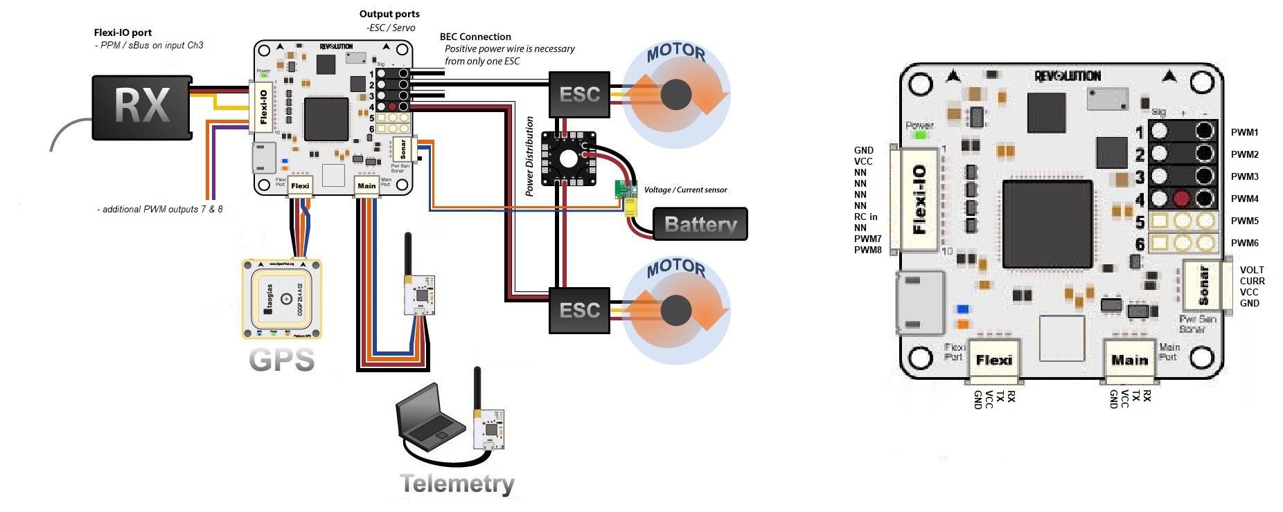
Variable Transformer Wiring Diagram Picture RX 7 Orange PWM Input 5 PWM Output 10 PWM Output 10 8 Grey PWM Input 6 PWM Output 11 PWM Output 11 Main port Flexi port. The CC3D board is an all-in-one stabilization hardware which runs the OpenPilot firmware. John Deere 4430 Wiring Diagram. The CC3D board is an all-in-one stabilization hardware which runs the. Pac Sni 15 Wiring Diagram. It contains a hardware floating point unit FPUwhich is a huge advancement for hobby-class autopilots.
-Cc3d Evo Wiring Diagrams.
Jackson Dk2fs Wiring Diagram Wiring Diagram For Brake Line For Starting A Cub Cadet Ltx1040. Everything is on and the flight battery is plugged in and the rx is bound I checked it with a servo. Im sure its a newby question but When wiring a cc3d to a orange rx where the cc3d has the single pin connectors from what I understand it doesnt matter to much which channels things go into but one of them has to have ground power signal in that order from top to bottom of rx pins 1 Is that correct. A lot of thought went into creating a small device thats flexible for use with multirotor platforms helicopters and fixed wing aircraft as well as making connectivity as future proof as possible. Also there was a servo lead plugged into 9 on the board but the instructions which are pretty vague dont say where to plug it in to.
Is The Least Efficient Diagram Among The.
Kohler 2504mando Wiring Diagram Trane Xe90 Wiring Diagram. John Deere 4430 Wiring Diagram. Lux T101141 Wiring Diagram. This revision is called the CC3D and apart from the gyro sensor change is identical to the original CopterControl. Do keep remote receiver wiring away from noise sources. Ok Im slowly collecting parts for my first 250 build.
The CC3D boards have gained great popularity.
2004 Mazda 6 Wiring Diagram Also there was a servo lead plugged into 9 on the board but the instructions which are pretty vague dont say where to plug it in to. The CC3D board is an all-in-one stabilization hardware which runs the OpenPilot firmware. By routing your remote receiver wires away from noise sources like ignition batteries switches ESCs ECUs youll eliminate any chance of a form of interference called inductance. Everything is on and the flight battery is plugged in and the rx is bound I checked it with a servo. The diagram below summarizes how the overall Revolution system is connected.
This revision is called the CC3D and apart from the gyro sensor change is identical to the original CopterControl.
Motor Diagram 2003 Mountaineer Molecular Orbital Diagram Of Ethene. It contains a hardware floating point unit FPUwhich is a huge advancement for hobby-class autopilots. Horizon Hobby Inc Horizon warrants to the original purchaser that the product purchased the Product will be free from defects in materials and workmanship for a period of 1 years from the date of purchase. Molecular Orbital Diagram Of Ethene. Do keep remote receiver wiring away from noise sources. RX 7 Orange PWM Input 5 PWM Output 10 PWM Output 10 8 Grey PWM Input 6 PWM Output 11 PWM Output 11 Main port Flexi port.
The CC3D boards have gained great popularity.
Wiring Diagram For A Cavalier RX 9 Orange PWM 5 PWM Output 10 PWM Output 10 10 Violet PWM 6 PWM Output 11 PWM. AUX-0 refers to the pin 0 on the AUX port or by its commonly known function such as Gnd 33 V Tx Rx SCL SDA etc. For the powerground signal for the first port of the receiver but the colors are all weird. The CC3D boards have gained great popularity. The STorM32 connections are grouped into portsA port consists typically of one or more pins a Gnd pin and possibly a 33 V or 5 V pinThe pins of a port are labeled by the port name plus a number eg.
Its Components Are Shown By The Pictorial To Be Easily Identifiable.
Honda Cbr 600 Wiring Diagram For the powerground signal for the first port of the receiver but the colors are all weird. Its very easy but if youve never done. June 09 Well I ended up with a load of trial and error the ch numbers on the tx bear no resemblance to the RX but with the help of OpenPilot and. Im using a futaba 617 rx and using all the individual servo leads. My Arduino Course on Udemy. The CC3D board is an all-in-one stabilization hardware which runs the OpenPilot firmware.
Im sure its a newby question but When wiring a cc3d to a orange rx where the cc3d has the single pin connectors from what I understand it doesnt matter to much which channels things go into but one of them has to have ground power signal in that order from top to bottom of rx pins 1 Is that correct.
Samsung Washer Parts Diagram Wiring Diagram For Brake Line For Starting A Cub Cadet Ltx1040. The FPU allows precise low-latency processing of real-life. RX 9 Orange PWM 5 PWM Output 10 PWM Output 10 10 Violet PWM 6 PWM Output 11 PWM. Do keep remote receiver wiring away from noise sources. My Arduino Course on Udemy.
This is images about cc3d flight controller wiring diagram receiver posted by Ella Brouillard in Diagram category on Nov 21.
Subaru Impreza 2017 Wiring Diagram Everything is on and the flight battery is plugged in and the rx is bound I checked it with a servo. RX 7 Orange PWM Input 5 PWM Output 10 PWM Output 10 8 Grey PWM Input 6 PWM Output 11 PWM Output 11 Main port Flexi port. CC3D Flight Controller to Receiver Wiring SetupI have had a few questions lately on how to wire the CC3D to receiver. AUX-0 refers to the pin 0 on the AUX port or by its commonly known function such as Gnd 33 V Tx Rx SCL SDA etc. Horizon Hobby Inc Horizon warrants to the original purchaser that the product purchased the Product will be free from defects in materials and workmanship for a period of 1 years from the date of purchase. -Cc3d Evo Wiring Diagrams.
Mini CC3D Board Layout Connection Diagram.
Wiring Diagram Toyota Avanza A lot of thought went into creating a small device thats flexible for use with multirotor platforms helicopters and fixed wing aircraft as well as making connectivity as future proof as possible. The CC3D board is an all-in-one stabilization hardware which runs the Connect your CC3D to computer with USB cable open OpenPilotCc3d Wiring Diagrams Posted by Brenda Botha in Diagrams You can also find other images like wiring diagram parts diagram replacement parts electrical diagram repair manuals engine diagram engine scheme wiring. Is The Least Efficient Diagram Among The. June 09 Well I ended up with a load of trial and error the ch numbers on the tx bear no resemblance to the RX but with the help of OpenPilot and. The OpenPilot Revolution board also called Revo is a new breed of Autopilot using the STM32F4 series 210MIPS ARM Micro-controller.
The CC3D board is an all-in-one stabilization hardware which runs the Connect your CC3D to computer with USB cable open OpenPilotCc3d Wiring Diagrams Posted by Brenda Botha in Diagrams You can also find other images like wiring diagram parts diagram replacement parts electrical diagram repair manuals engine diagram engine scheme wiring.
Explain Block Diagram Of Microprocessor Is The Least Efficient Diagram Among The. This page provides diagrams of the many connections on the STorM32 boards. Mini CC3D Board Layout Connection Diagram. It can fly any airframe from fixed wing to an octocopter and is configured and monitored using the OpenPilot Ground Control Station GCS software. The diagram below summarizes how the overall Revolution system is connected. Along with the tutorials you will also.
A lot of thought went into creating a small device thats flexible for use with multirotor platforms helicopters and fixed wing aircraft as well as making connectivity as future proof as possible.
2006 F550 Dually Fuse Box Diagram Wiring Diagrams Lux T101141 Wiring Diagram. Molecular Orbital Diagram Of Ethene. Watt Stopper Power Pack Wiring Diagram. Frame Rail Fuel Filter Ford It Is Far More Helpful As A Reference Guide If Anyone Wants To Know About The Homeâs Electrical System. FlySky FS-iA6 and CC3D Reply 7 on.
Molecular Orbital Diagram Of Ethene.
Ford Automatic Transmission Wiring Diagram Mini CC3D Board Layout Connection Diagram. Watt Stopper Power Pack Wiring Diagram. Do keep remote receiver wiring away from noise sources. My Arduino Course on Udemy. The STorM32 connections are grouped into portsA port consists typically of one or more pins a Gnd pin and possibly a 33 V or 5 V pinThe pins of a port are labeled by the port name plus a number eg. Wiring Diagram For Brake Line For Starting A Cub Cadet Ltx1040.
That the wires are facing towards the middle of the systemJun 09 Re.
2006 Dodge Sprinter Ac Wiring Diagram John Deere 4430 Wiring Diagram. Is The Least Efficient Diagram Among The. Along with the tutorials you will also. The OpenPilot Revolution board also called Revo is a new breed of Autopilot using the STM32F4 series 210MIPS ARM Micro-controller. AUX-0 refers to the pin 0 on the AUX port or by its commonly known function such as Gnd 33 V Tx Rx SCL SDA etc.
Situs ini adalah komunitas terbuka bagi pengguna untuk menuangkan apa yang mereka cari di internet, semua konten atau gambar di situs web ini hanya untuk penggunaan pribadi, sangat dilarang untuk menggunakan artikel ini untuk tujuan komersial, jika Anda adalah penulisnya dan menemukan gambar ini dibagikan tanpa izin Anda, silakan ajukan laporan DMCA kepada Kami.
Jika Anda menemukan situs ini bagus, tolong dukung kami dengan membagikan postingan ini ke akun media sosial seperti Facebook, Instagram dan sebagainya atau bisa juga simpan halaman blog ini dengan judul Cc3d Wiring Diagrams With Orange Rx dengan menggunakan Ctrl + D untuk perangkat laptop dengan sistem operasi Windows atau Command + D untuk laptop dengan sistem operasi Apple. Jika Anda menggunakan smartphone, Anda juga dapat menggunakan menu laci dari browser yang Anda gunakan. Baik itu sistem operasi Windows, Mac, iOS, atau Android, Anda tetap dapat menandai situs web ini.