Solid State Relay Wiring Diagram For Cut Out - Jika kamu sedang mencari artikel Solid State Relay Wiring Diagram For Cut Out terbaru, berarti kamu sudah berada di web yang tepat. Setiap artikel dibahas secara tuntas dengan penyajian bahasa yang gampang dimengerti bagi orang awam sekalipun. itulah sebabnya website ini banyak diminati para blogger dan pembaca online. Yuk langsung saja kita simak pembahasan Solid State Relay Wiring Diagram For Cut Out berikut ini.
Solid State Relay Wiring Diagram For Cut Out. The diagram shows the relay in the relaxed state. 8B RELAY OUTPUTS 4 5 and 10 TO 14 WIRING Fig. This article provides an introduction to the basic operation of solid-state relays with a focus on the output devices in todays SSRs. 1 below shows the basic wiring diagram for testing a DC input solid state relay. To get a sizable relay for your use spec it out.
Mazda 3 Navigation Wiring Diagram 12 Volt Wiring Diagram Best 12v Relay Pin 5 and Roc Grp org In. Here you can see the heater is operating with a 230V AC supply. Downloads Staging Brake Control Relay Diagram Features This relay can be used for the following. FT600 FT550 FT500 FT500LITE FT450 built-in Staging Control FT600 FT550 FT500 FT500LITE FT450 built-in Brake Control Fast switching speed which is perfect for PWM control and for use as a normal relay. To get a sizable relay for your use spec it out. Connect R positive terminal to the push button.
Enable downsizing of multi-pole relays.
Wiring Diagram Ford Fiesta Rocam 2011 Downloads Staging Brake Control Relay Diagram Features This relay can be used for the following. If someone would share the wiring diagram it would be great. 12 Volt Relay Wiring Diagram - Collections Of Best Relay Wiring Diagram 5 Pin Bosch Endearing Enchanting Blurts. These delays must all be considered when determining the switching frequency. Early types of electrical isolation were by large mechanical master-switches while more modern systems have utilised electro-mechanical solenoidsBoth of these types of systems contain mechanical electrical contacts which due to the combination of high electrical current and the shocks and vibration of the race car. Solid State Relay Optocoupler Relay.
8C RELAY OUTPUTS 15 TO 19 WIRING Outputs from OUT 10 to OUT 19 are optional.
Baldor Motor Wiring Diagrams 110v Two Direction If someone would share the wiring diagram it would be great. Please refer to the repair manual or workshop manual for repair and testing of the generator. Hvac Fan Relay Wiring Diagram Download. Here you can see the Solid State Relay Wiring Connection Diagram for the automatic control of an electric heater. What is Solid State Relay SSR.
General-purpose Relay Solid State Relay SSR Features Compact More compact than an SSR when the same load capacity is controlled.
1975 F250 Wiring Diagram 4785-38 model cut-out relay. The contact rating from OUT 1 and OUT 2 is 3A250V AC on resistive load. To get a sizable relay for your use spec it out. Connect R positive terminal to the push button. Solid state relay SSR is an electronic switching device made of semiconductors that switch On Off a high voltage circuit using a low voltage at its control terminalsUnlike EMR Electromagnetic relay that has a coil mechanical switch physical contacts the SSR relay uses Optocoupler to isolate the control circuit from the controlled circuit. These relays are the same as the hinged relays described previously except that the core yoke and armature are made from semi-hard magnetic material and there are at least two coils in the relay.
Please note that the diagram refers to DCDC type solid state relay SSR.
Fender Telecaster Guitar Wiring Diagrams FT600 FT550 FT500 FT500LITE FT450 built-in Staging Control FT600 FT550 FT500 FT500LITE FT450 built-in Brake Control Fast switching speed which is perfect for PWM control and for use as a normal relay. The diagram shows the relay in the relaxed state. The diagram below shows how to wire a solid state relay. General-purpose Relay Solid State Relay SSR Features Compact More compact than an SSR when the same load capacity is controlled. What is Solid State Relay SSR.
For much higher voltages an SSR is an excellent alternative when a regular switch cannot be used because of burn out under the current.
Chevrolet Cruze Wiring Diagram 8B RELAY OUTPUTS 4 5 and 10 TO 14 WIRING Fig. Solid State Relay DCDC. Two circuit diagrams showing the improper and proper ways of switching mains electricity with a relay. Triac is used at the place of coil relay to switch ON and OFF. Please note that the diagram refers to DCDC type solid state relay SSR. Early types of electrical isolation were by large mechanical master-switches while more modern systems have utilised electro-mechanical solenoidsBoth of these types of systems contain mechanical electrical contacts which due to the combination of high electrical current and the shocks and vibration of the race car.
Solid State Relay DCDC.
199Mazda 929 Service Repair Shop Manual Set Oem 9Service Manual And The Wiring Diagrams Manual These relays are the same as the hinged relays described previously except that the core yoke and armature are made from semi-hard magnetic material and there are at least two coils in the relay. FT600 FT550 FT500 FT500LITE FT450 built-in Staging Control FT600 FT550 FT500 FT500LITE FT450 built-in Brake Control Fast switching speed which is perfect for PWM control and for use as a normal relay. If someone would share the wiring diagram it would be great. Hvac Fan Relay Wiring Diagram Download. Here you can see the heater is operating with a 230V AC supply.
Best Bosch Relay Wiring Diagram 5 Pole Electrical Outlet Symbol 2018.
1968 Camaro Wiring Harness Diagram When the AC mains is applied to the output of the. 1 below shows the basic wiring diagram for testing a DC input solid state relay. Two circuit diagrams showing the improper and proper ways of switching mains electricity with a relay. Sainsmart relay boards are nice because they have optoisolators protection diodes and relays and little leds all packaged pretty cheap. They are represented by the dotted lines in the wiring diagrams. In this there is only semiconductor devices used no Mechanical coil relay is used to Switching the Connected Load.
Sainsmart relay boards are nice because they have optoisolators protection diodes and relays and little leds all packaged pretty cheap.
2013 Volkswagen Jetta S Fuse Diagram 1 below shows the basic wiring diagram for testing a DC input solid state relay. The contact rating from OUT 1 and OUT 2 is 3A250V AC on resistive load. When the AC mains is applied to the output of the. Loads such as inductive loads also have delay times called the operating time and release time. 8B RELAY OUTPUTS 4 5 and 10 TO 14 WIRING Fig.
These delays must all be considered when determining the switching frequency.
Volvo 850 Wiring Diagram De Taller What is Solid State Relay SSR. Early types of electrical isolation were by large mechanical master-switches while more modern systems have utilised electro-mechanical solenoidsBoth of these types of systems contain mechanical electrical contacts which due to the combination of high electrical current and the shocks and vibration of the race car. Your Load will probably be inductive if it is built around a large coil of wire - motors and transformers. 12 Volt Wiring Diagram Best 12v Relay Pin 5 and Roc Grp org In. Every time delay relay has an internal relay usually mechanical with contacts that open close to control the load. Best Bosch Relay Wiring Diagram 5 Pole Electrical Outlet Symbol 2018.
Enable high-speed and high-frequency switching.
Beyond The First Draft The Art Of Fiction For much higher voltages an SSR is an excellent alternative when a regular switch cannot be used because of burn out under the current. 8C RELAY OUTPUTS 15 TO 19 WIRING Outputs from OUT 10 to OUT 19 are optional. The diagram below shows how to wire a solid state relay. Enable downsizing of multi-pole relays. Here you can see the heater is operating with a 230V AC supply.
In this there is only semiconductor devices used no Mechanical coil relay is used to Switching the Connected Load.
2002 Lexus Ls 430 Wiring Harness Diagram Two circuit diagrams showing the improper and proper ways of switching mains electricity with a relay. Loads such as inductive loads also have delay times called the operating time and release time. Enable downsizing of multi-pole relays. 15A is big pumps switch slow and ratings are reliable. Solid State Relay DCDC. Solid state relays SSRs turn on or off the power being supplied to other devices in a similar fashion as a physical switch.
General-purpose Relay Solid State Relay SSR Features Compact More compact than an SSR when the same load capacity is controlled.
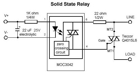
1973 Vw Bus Wiring Diagram 12 Volt Relay Wiring Diagram - Collections Of Best Relay Wiring Diagram 5 Pin Bosch Endearing Enchanting Blurts. 8C RELAY OUTPUTS 15 TO 19 WIRING Outputs from OUT 10 to OUT 19 are optional. 1 below shows the basic wiring diagram for testing a DC input solid state relay. Our replacement for these old cut-out is the 6 Volt solid state Relay as shown below in the figure. Solid State Relay is a type of switch to activate Load by using without any Mechanical parts.
Solid state relay SSR is an electronic switching device made of semiconductors that switch On Off a high voltage circuit using a low voltage at its control terminalsUnlike EMR Electromagnetic relay that has a coil mechanical switch physical contacts the SSR relay uses Optocoupler to isolate the control circuit from the controlled circuit.
93 Honda Civic Fuse Box Diagram 8C RELAY OUTPUTS 15 TO 19 WIRING Outputs from OUT 10 to OUT 19 are optional. Every time delay relay has an internal relay usually mechanical with contacts that open close to control the load. These delays must all be considered when determining the switching frequency. FT600 FT550 FT500 FT500LITE FT450 built-in Staging Control FT600 FT550 FT500 FT500LITE FT450 built-in Brake Control Fast switching speed which is perfect for PWM control and for use as a normal relay. Enable high-speed and high-frequency switching. Connect R positive terminal to the push button.
The contact rating from OUT 1 and OUT 2 is 3A250V AC on resistive load.
Camaro 82 Wiring Diagram 12 Volt Wiring Diagram Best 12v Relay Pin 5 and Roc Grp org In. What is Solid State Relay SSR. The diagram shows the relay in the relaxed state. Solid State Relays Common Precautions Solid State Relays Common Precautions 3ONOFF Frequency An SSR has delay times called the operating time and release time. Solid State Relay is a type of switch to activate Load by using without any Mechanical parts.
There are many circumstances in which we need to control a high currentvoltage load based on the operation of a low-power circuit such as when using the 5V output of a microcontroller to turn on a 10A 240V load.
A F Sensor Toyota Wiring Diagram The contact rating of OUT 5 is 1A250V AC on resistive load. The contact rating from OUT 3 and OUT 4 is 2A250V AC on resistive load. Our replacement for these old cut-out is the 6 Volt solid state Relay as shown below in the figure. Connect R positive terminal to the push button. I would like to use my transbrake bump box for staging. 12 Volt Wiring Diagram Best 12v Relay Pin 5 and Roc Grp org In.
General-purpose Relay Solid State Relay SSR Features Compact More compact than an SSR when the same load capacity is controlled.
Ford F150 Trailer Lights Wiring Diagram 8C RELAY OUTPUTS 15 TO 19 WIRING Outputs from OUT 10 to OUT 19 are optional. Solid State means no moving parts all power switching is fully electronic. Best Bosch Relay Wiring Diagram 5 Pole Electrical Outlet Symbol 2018. Loads such as inductive loads also have delay times called the operating time and release time. Solid State Relay DCDC.
Situs ini adalah komunitas terbuka bagi pengguna untuk berbagi apa yang mereka cari di internet, semua konten atau gambar di situs web ini hanya untuk penggunaan pribadi, sangat dilarang untuk menggunakan artikel ini untuk tujuan komersial, jika Anda adalah penulisnya dan menemukan gambar ini dibagikan tanpa izin Anda, silakan ajukan laporan DMCA kepada Kami.
Jika Anda menemukan situs ini bagus, tolong dukung kami dengan membagikan postingan ini ke akun media sosial seperti Facebook, Instagram dan sebagainya atau bisa juga save halaman blog ini dengan judul Solid State Relay Wiring Diagram For Cut Out dengan menggunakan Ctrl + D untuk perangkat laptop dengan sistem operasi Windows atau Command + D untuk laptop dengan sistem operasi Apple. Jika Anda menggunakan smartphone, Anda juga dapat menggunakan menu laci dari browser yang Anda gunakan. Baik itu sistem operasi Windows, Mac, iOS, atau Android, Anda tetap dapat menandai situs web ini.