Uln2003 Logic Diagram - Jika kamu sedang mencari artikel Uln2003 Logic Diagram terbaru, berarti kamu sudah berada di website yang benar. Setiap artikel dibahas secara lengkap dengan penyajian bahasa yang mudah dipahami bagi orang awam sekalipun. itulah sebabnya website ini banyak diminati para blogger dan pembaca online. Yuk langsung saja kita simak penjelasan Uln2003 Logic Diagram berikut ini.
Uln2003 Logic Diagram. For 100-V otherwise interchangeable versions of the ULx2003A devices see the SLRS023 data sheet for the SN75468 and SN75469 devices. It is a monolithic IC consists of seven NPN Darlington transistor pair. This makes the ULN 2003 IC suitable for switching inductive loads. Soic16 case 751b05 issue k scale 11 date 29 dec 2006 notes. Dimensioning and tolerancing per ansi y145m 1982.
1984 Jeep Wiring Diagram 28BYJ-48 28BYJ-48 unipolar stepper motor. Each pair is rated for 50V and 500mA. ULN2003A pinout and functional diagram. Pin 11 Arduino Logic GND Arduino. Each input of this device has a Zener diode and resistor in series to. Can be directly controlled by logic devices like Digital Gates Arduino PIC etc.
ULN2003 and 28BYJ-48 to Arduino Connections.
Wiring Cnc Diagram Controller 4060z Pinout and logic diagram for the ULN2003AD from Texas Instruments datasheet. ULN2003 is a 16 Pin IC consisting of 7 darlington pairs each pair protected with supression diode and thus has the capability to handle maximum 7 loads could be inductive. You can see how the resistors and diodes are connected with each other. Can be directly controlled by logic devices like Digital Gates Arduino PIC etc. Efficient to use Logic Buffer in mostly Digital Electronics. The 28YBJ-48 stepper motor operates on 5Vdc and has built-in reduction gears.
The collector-current rating of a single Darlington pair is 500 mA.
3000gt Spark Plug Diagram Wiring Schematic Schematic diagram ULN2001 each driver ULN2002 each driver. Logic buffers and many others Diagram of relay driver circuit using uln2003. It has good torque for its size but has relatively slow. ULN2003 LOGIC DIAGRAM ULN2003 internal circuit and Pin Configuration The internal circuit uses connecting Darlington transistor. Arduino ULN2003A based stepper driver board.
Input pins can be triggered by 5V.
Ppt Of Block Diagram Reduction It features common-cathode flyback diodes for switching inductive loads. In simple words we have 7 drivers in a single ULN2003 chip and thus can control maximum 7 loads. ULN 2003 IC belongs to the family of ULN 200X series if ICs. Thus when a 5V is given to 1B terminal 1C terminal will be connected to ground via darlington pair and the maximum current that it can handle is 500A. Diagram of relay driver circuit using uln2003 The relay driver circuit using uln2003 is given below. Input pins can be triggered by 5V.
Generally this IC is used in 5V TTL CMOS devices.
In Dash Tv Wiring Diagram Efficient to use Logic Buffer in mostly Digital Electronics. ULN2003 is a 16 Pin IC consisting of 7 darlington pairs each pair protected with supression diode and thus has the capability to handle maximum 7 loads could be inductive. It is mostly used to control the stepper motor. Diagram of relay driver circuit using uln2003 The relay driver circuit using uln2003 is given below. It features common-cathode flyback diodes for switching inductive loads.
This makes the ULN 2003 IC suitable for switching inductive loads.
Lb27 Electric Scooter Controller Wiring Diagram High load LED Bulbs can be controlled through it. It features common-cathode flyback diodes for switching inductive loads. Inputs compatible with TTL and 5V CMOS logic. In simple words we have 7 drivers in a single ULN2003 chip and thus can control maximum 7 loads. Pin 11 Arduino Logic GND Arduino. TPIC2701 ULN2001 ULN2002 ULN2004 L293D Motor Driver Shield Where to use a ULN2003.
Input pins can be triggered by 5V.
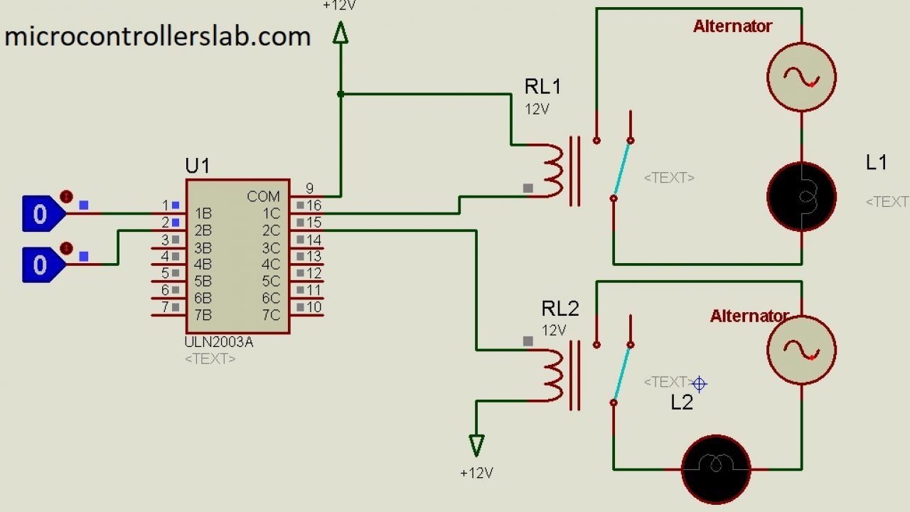
2002 Infiniti I35 Wiring Diagram This IC consists of common cathode clamp diodes for each NPN Darlington pair. In this circuit diagram pic microcontroller is providing signal to 4 relays through relay driver IC uln2003. ULN2003 LOGIC DIAGRAM ULN2003 internal circuit and Pin Configuration The internal circuit uses connecting Darlington transistor. In simple words we have 7 drivers in a single ULN2003 chip and thus can control maximum 7 loads. I used a breadboard and some jumper wires to connect the driver board to an external power supply.
It is a monolithic IC consists of seven NPN Darlington transistor pair.
Rg570 Wiring Diagram This IC consists of common cathode clamp diodes for each NPN Darlington pair. It has wide use as a torch sensor with the. The ULN2002A device is designed specifically for use with 14-V to 25-V PMOS devices. It has good torque for its size but has relatively slow. This makes the ULN 2003 IC suitable for switching inductive loads. 7-relays can be controlled with a single ULN2003.
Resulting in using only a small amount of current to drive the relay.
Cx 7 Stereo Wiring Diagram Each channel rated at. TPIC2701 ULN2001 ULN2002 ULN2004 L293D Motor Driver Shield Where to use a ULN2003. Efficient to use Logic Buffer in mostly Digital Electronics. Schematic diagram ULN2001 each driver ULN2002 each driver. For 100-V otherwise interchangeable versions of the ULx2003A devices see the SLRS023 data sheet for the SN75468 and SN75469 devices.
The ULN2003 is designed to interface with TTL and CMOS devices and the output can be used to drive loads up to 50 V and 500 mA.
Apple Tv Wiring Diagram ULN2003 LOGIC DIAGRAM ULN2003 internal circuit and Pin Configuration The internal circuit uses connecting Darlington transistor. This IC consists of common cathode clamp diodes for each NPN Darlington pair. The ULN2003A is an array of seven NPN Darlington transistors capable of 500 mA 50 V output. Dimensioning and tolerancing per ansi y145m 1982. Pin 11 Arduino Logic GND Arduino. ULN2803 Logic Diagram Following figure shows the logic diagram of ULN2803.
The ULN2003A is an array of seven NPN Darlington transistors capable of 500 mA 50 V output.
Asco 911 Wiring Diagram I used a breadboard and some jumper wires to connect the driver board to an external power supply. ULN2003 and 28BYJ-48 to Arduino Connections. The ULN2002A device is designed specifically for use with 14-V to 25-V PMOS devices. If we make the above circuit diagram using transistors it will be very difficult to design this circuit. LED and gas discharge line drivers and logic buffers.
Soic16 case 751b05 issue k scale 11 date 29 dec 2006 notes.
42 Vizio Tv Schematic Diagram Pinout and logic diagram for the ULN2003AD from Texas Instruments datasheet. The collector-current rating of a single Darlington pair is 500 mA. Arduino ULN2003A based stepper driver board. Can be directly controlled by logic devices like Digital Gates Arduino PIC etc. Logic buffers and many others Diagram of relay driver circuit using uln2003. This IC consists of common cathode clamp diodes for each NPN Darlington pair.
ULN2003 is a 16 Pin IC consisting of 7 darlington pairs each pair protected with supression diode and thus has the capability to handle maximum 7 loads could be inductive.
Wiring Diagram For A 1987 Ford F150 In simple words we have 7 drivers in a single ULN2003 chip and thus can control maximum 7 loads. Logic Diagram Applications Relay Drivers Hammer Drivers Lamp Drivers Line Drivers Logic Buffers Stepper Motors IP Camera HVAC Valve and LED Dot Matrix Description ULN2003 is high voltage high current darlington arrays each containing seven open collector darlington pairs with common emitters. Resulting in using only a small amount of current to drive the relay. In this circuit diagram pic microcontroller is providing signal to 4 relays through relay driver IC uln2003. Diagram of relay driver circuit using uln2003 The relay driver circuit using uln2003 is given below.
As can be seen above the ULN2003 is a 16-pin IC with seven Darlington pairs.
Outdoor Motion Sensor Light Switch Wiring Diagram The ULN2003A is a high-voltage high-current Darlington transistor array consisting of seven NPN Darlington pairs that feature high-voltage outputs with common-cathode clamp diodes for switching inductive loads. It features common-cathode flyback diodes for switching inductive loads. Inductive loads are also easy to control by using ULN2003. The collector-current rating of a single Darlington pair is 500 mA. I used a breadboard and some jumper wires to connect the driver board to an external power supply. The 28YBJ-48 stepper motor operates on 5Vdc and has built-in reduction gears.
Soic16 case 751b05 issue k scale 11 date 29 dec 2006 notes.
6 Pin Rocker Switch Wiring Diagram Free Picture 5 6 or 8 wire stepper motor ie. Each channel rated at. ULN2003 IC is one of the most commonly used Motor driver ICThis IC comes in handy when we need to drive high current loads using digital logic circuits like Op-maps Timers Gates Arduino PIC ARM etc. Inductive loads are also easy to control by using ULN2003. ULN2803 Logic Diagram Following figure shows the logic diagram of ULN2803.
Soic16 case 751b05 issue k scale 11 date 29 dec 2006 notes.
Ford Taurus Ohv Engine Diagram ULN2803 Logic Diagram Following figure shows the logic diagram of ULN2803. Inductive loads are also easy to control by using ULN2003. Efficient to use Logic Buffer in mostly Digital Electronics. 28BYJ-48 28BYJ-48 unipolar stepper motor. ULN2003 and 28BYJ-48 to Arduino Connections. Resulting in using only a small amount of current to drive the relay.
It is a visual representation and arrangement of how the diodes are connected in the component.
Single Phase Motor Wiring Diagram For A Switch The ULN2003A is an array of seven NPN Darlington transistors capable of 500 mA 50 V output. This IC consists of common cathode clamp diodes for each NPN Darlington pair. Efficient to use Logic Buffer in mostly Digital Electronics. Relay driver circuit using uln2003 is given below. As can be seen above the ULN2003 is a 16-pin IC with seven Darlington pairs.
Situs ini adalah komunitas terbuka bagi pengguna untuk berbagi apa yang mereka cari di internet, semua konten atau gambar di situs web ini hanya untuk penggunaan pribadi, sangat dilarang untuk menggunakan artikel ini untuk tujuan komersial, jika Anda adalah penulisnya dan menemukan gambar ini dibagikan tanpa izin Anda, silakan ajukan laporan DMCA kepada Kami.
Jika Anda menemukan situs ini bagus, tolong dukung kami dengan membagikan postingan ini ke akun media sosial seperti Facebook, Instagram dan sebagainya atau bisa juga simpan halaman blog ini dengan judul Uln2003 Logic Diagram dengan menggunakan Ctrl + D untuk perangkat laptop dengan sistem operasi Windows atau Command + D untuk laptop dengan sistem operasi Apple. Jika Anda menggunakan smartphone, Anda juga dapat menggunakan menu laci dari browser yang Anda gunakan. Baik itu sistem operasi Windows, Mac, iOS, atau Android, Anda tetap dapat menandai situs web ini.