Block Diagram Basic Organizationputer System - Jika kamu mencari artikel Block Diagram Basic Organizationputer System terbaru, berarti kamu telah berada di website yang benar. Setiap artikel diulas secara mendetail dengan penyajian bahasa yang mudah dimengerti bagi orang awam sekalipun. itulah sebabnya web site ini banyak diminati para blogger dan pembaca online. Yuk langsung saja kita simak penjelasan Block Diagram Basic Organizationputer System berikut ini.
Block Diagram Basic Organizationputer System. The set of instruction is presented to the computer in the form of raw data which is entered through input devices such as keyboard or mouse. Figure 3-46 Block diagram of a system. It is not always convenient to derive the entire transfer function of a complex control system in a single function. Consider a series of RLC circuit as shown in the following figure. Let it be the current passing through the circuit.
Lg G3 Diagram Use the libraries from the Block Diagrams solution to draw block diagrams for your business documents presentations and websites in a few minutes. This is the introductory video on Analog and Digital Communication. A computer can process a large volume of data and produce a desirable result. As we know a communication system serves to communicate a message or information. When we get inside working of computer we find that there are different hardware components categorized under different types or unit playing their roles to support the overall processing of a computer system. The block diagram is to represent a control system in diagram form.
Figure 3-46 Block diagram of a system.
2002 Silverado Interior Wiring Diagram A computer can process a large volume of data and produce a desirable result. Consider a series of RLC circuit as shown in the following figure. It consists of a single block with one input and one output Figure 1A. Block Diagram of Computer System. The block diagram of a communication system will have five blocks including the information source transmitter channel receiver and destination blocks. Block diagram of computer.
22451 Dynamic Systems Block Diagrams Block Diagram Representation Summing JunctionUsed to sum signals together x1 x3 x2 x1 x2 x3 Constant GainScalar multiplier k x1 kx1 ms cs k 1 2 ft xt Transfer FunctionGvein a system with zero initial conditions the transfer function is the ratio of output due to input.
Subaru Sti Fuse Box Diagram _draw A Block Diagram To Illustrate The Basic Organization Of A Computer System. _draw A Block Diagram To Illustrate The Basic Organization Of A Computer System. Initially the transmitting tubes were not that much powerful thus worked at a very low frequency of about 60 MHz. In this section let us represent an electrical system with a block diagram. I The necessary components of a communication system are an information source input transducer transmitter communication channel receiver and destination.
Initially the transmitting tubes were not that much powerful thus worked at a very low frequency of about 60 MHz.
2012 Chevy Silverado 1500 Wiring Diagram As we know a communication system serves to communicate a message or information. Figure 3-46 Block diagram of a system. System block diagrams enable one to visualize the system as large interacting. Block Diagram of Computer System. _draw A Block Diagram To Illustrate The Basic Organization Of A Computer System. Now we shall discuss the functioning of these blocks.
Create block diagrams electrical circuit diagrams schematics and more in minutes with ConceptDraw PRO.
Beverage Air Kf48 1as Wiring Diagram When we get inside working of computer we find that there are different hardware components categorized under different types or unit playing their roles to support the overall processing of a computer system. I shows the block diagram of a general communication system in which the different functional elements are represented by blocks. 22451 Dynamic Systems Block Diagrams Block Diagram Representation Summing JunctionUsed to sum signals together x1 x3 x2 x1 x2 x3 Constant GainScalar multiplier k x1 kx1 ms cs k 1 2 ft xt Transfer FunctionGvein a system with zero initial conditions the transfer function is the ratio of output due to input. Let it be the current passing through the circuit. Where V i t and V o t are the input and output voltages.
I shows the block diagram of a general communication system in which the different functional elements are represented by blocks.
Bus Flasher Wiring Diagram A computer can process a large volume of data and produce a desirable result. Block diagram shown in Figure 3-44. I shows the block diagram of a general communication system in which the different functional elements are represented by blocks. The set of instruction is presented to the computer in the form of raw data which is entered through input devices such as keyboard or mouse. But further development in the field and use of magnetrons has extended the. A computer takes help of a different device to perform a different job.
Let it be the current passing through the circuit.
Direct Tv Satellite Wiring Diagrams I The necessary components of a communication system are an information source input transducer transmitter communication channel receiver and destination. Let it be the current passing through the circuit. Create block diagrams electrical circuit diagrams schematics and more in minutes with ConceptDraw PRO. Block Diagram Representation of Electrical Systems. A block diagram provides a means to easily identify the functional relationships among the various components of a control system.
Block diagrams solution extends ConceptDraw PRO software with templates samples and libraries of vector stencils for creating the block diagram.
3 Prong Schematic Wiring Diagram This is the process of entering data and programs in to the computer systemYou should know that computer is an electronic machine like any other machine which takes as inputs raw data and performs some processing giving out processed data. I shows the block diagram of a general communication system in which the different functional elements are represented by blocks. In this section let us represent an electrical system with a block diagram. Eliminating the minor feedforward path we obtain Figure 3-45b which can be simplified to that shown in Figure 3--5cThe transfer function CsRs is thus given by. A system block diagram is a high level modularization of the system that separates the overall system into maximally decoupled sub-systems. It consist of primary sensing element variable manipulation element data transmission element and data presentation element.
Radar was invented for military purpose before world war II in order to secretly detect the presence of unknown objects.
Kubota Work Light Wiring Diagram When we get inside working of computer we find that there are different hardware components categorized under different types or unit playing their roles to support the overall processing of a computer system. I The necessary components of a communication system are an information source input transducer transmitter communication channel receiver and destination. Figure 3-46 Block diagram of a system. In this section let us represent an electrical system with a block diagram. Block Diagram of Basic Communication System.
In other words practical representation of a control system is its block diagram.
1967 Chevelle Diagram System block diagrams enable one to visualize the system as large interacting. A computer takes help of a different device to perform a different job. This is the introductory video on Analog and Digital Communication. Block Diagram Representation of Electrical Systems. When we get inside working of computer we find that there are different hardware components categorized under different types or unit playing their roles to support the overall processing of a computer system. Use the libraries from the Block Diagrams solution to draw block diagrams for your business documents presentations and websites in a few minutes.
Block Diagram of Basic Communication System.
Winnebago Wiring Diagram Picture Schematic Use the libraries from the Block Diagrams solution to draw block diagrams for your business documents presentations and websites in a few minutes. System block diagrams enable one to visualize the system as large interacting. Eliminating the minor feedforward path we obtain Figure 3-45b which can be simplified to that shown in Figure 3--5cThe transfer function CsRs is thus given by. A computer can process a large volume of data and produce a desirable result. This is the process of entering data and programs in to the computer systemYou should know that computer is an electronic machine like any other machine which takes as inputs raw data and performs some processing giving out processed data.
When we get inside working of computer we find that there are different hardware components categorized under different types or unit playing their roles to support the overall processing of a computer system.
1995 Toyota Paseo Engine Diagram The block diagram of a communication system will have five blocks including the information source transmitter channel receiver and destination blocks. The set of instruction is presented to the computer in the form of raw data which is entered through input devices such as keyboard or mouse. Computer The word computer comes from the word compute which means to calculate. _draw A Block Diagram To Illustrate The Basic Organization Of A Computer System. Use the libraries from the Block Diagrams solution to draw block diagrams for your business documents presentations and websites in a few minutes. Now we shall discuss the functioning of these blocks.
Block diagrams solution extends ConceptDraw PRO software with templates samples and libraries of vector stencils for creating the block diagram.
Circuit Diagrams Eliminating the minor feedforward path we obtain Figure 3-45b which can be simplified to that shown in Figure 3--5cThe transfer function CsRs is thus given by. Let it be the current passing through the circuit. Create block diagrams electrical circuit diagrams schematics and more in minutes with ConceptDraw PRO. The block diagram shown above is of basic instrumentation system. The block diagram of Figure 3-44 can be modified to that shown in Figure 3-45a.
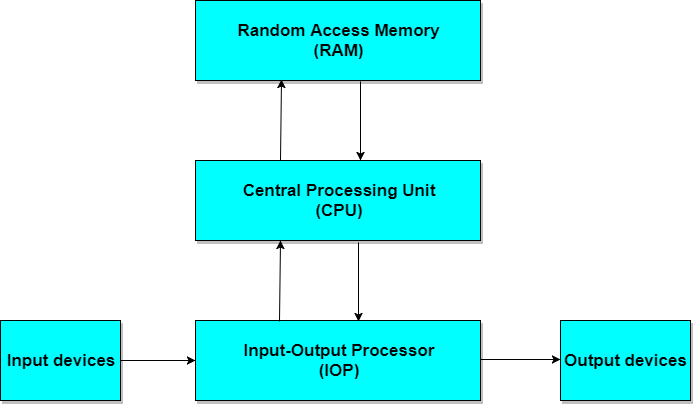
The Computer system consists of mainly three types that are central processing unit CPUInput Devices and Output DevicesThe Central processing unit CPU again consists of ALU Arithmetic Logic Unit and Control Unit.
Uln2003 Logic Diagram The set of instruction is presented to the computer in the form of raw data which is entered through input devices such as keyboard or mouse. Now we shall discuss the functioning of these blocks. _draw A Block Diagram To Illustrate The Basic Organization Of A Computer System. Therefore the input unit takes data from us to the computer in an organized manner for processing. Initially the transmitting tubes were not that much powerful thus worked at a very low frequency of about 60 MHz. A block diagram is a pictorial representation of the cause and effect relationship between the input and output of a physical system.
Electrical systems contain mainly three basic elements resistor inductor and capacitor.
Emg Wiring Diagrams 2 Volume 3 Way Figure 3-46 Block diagram of a system. I shows the block diagram of a general communication system in which the different functional elements are represented by blocks. As we know a communication system serves to communicate a message or information. It consists of a single block with one input and one output Figure 1A. It is not always convenient to derive the entire transfer function of a complex control system in a single function.
But further development in the field and use of magnetrons has extended the.
Snapper Lawn Tractor Lt145h38 Belt Diagram What is Basic Block Diagram of Computer System. Initially the transmitting tubes were not that much powerful thus worked at a very low frequency of about 60 MHz. I shows the block diagram of a general communication system in which the different functional elements are represented by blocks. Electrical systems contain mainly three basic elements resistor inductor and capacitor. Radar was invented for military purpose before world war II in order to secretly detect the presence of unknown objects. Block Diagram of Computer and its Various Components.
In this video the block diagram of the communication system as well as some of the term.
1997 Dodge Ram Headlight Wiring Diagram Block Diagram of Basic Communication System. Use the libraries from the Block Diagrams solution to draw block diagrams for your business documents presentations and websites in a few minutes. Block diagrams solution extends ConceptDraw PRO software with templates samples and libraries of vector stencils for creating the block diagram. What is Basic Block Diagram of Computer System. Block diagram shown in Figure 3-44.
Situs ini adalah komunitas terbuka bagi pengguna untuk menuangkan apa yang mereka cari di internet, semua konten atau gambar di situs web ini hanya untuk penggunaan pribadi, sangat dilarang untuk menggunakan artikel ini untuk tujuan komersial, jika Anda adalah penulisnya dan menemukan gambar ini dibagikan tanpa izin Anda, silakan ajukan laporan DMCA kepada Kami.
Jika Anda menemukan situs ini bagus, tolong dukung kami dengan membagikan postingan ini ke akun media sosial seperti Facebook, Instagram dan sebagainya atau bisa juga simpan halaman blog ini dengan judul Block Diagram Basic Organizationputer System dengan menggunakan Ctrl + D untuk perangkat laptop dengan sistem operasi Windows atau Command + D untuk laptop dengan sistem operasi Apple. Jika Anda menggunakan smartphone, Anda juga dapat menggunakan menu laci dari browser yang Anda gunakan. Baik itu sistem operasi Windows, Mac, iOS, atau Android, Anda tetap dapat menandai situs web ini.